
Frost Protected Shallow Footing for Raft Foundation Details – Cross Section and Isometric Plan
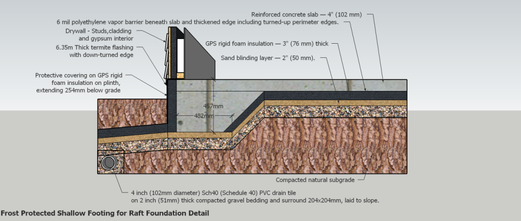
Cross Section – Frost Protected Shallow Footing for Raft Foundation
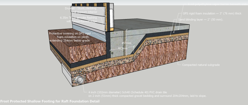
Isometric View – Frost Protected Shallow Footing for Raft Foundation
Dimensioning and Setting-Out Specification – Drafting Reference Notes
Frost Protected Shallow Foundation (FPSF) Raft Foundation Detail
3. Reference Levels and Datums
These establish where dimensions are measured from.
Primary Vertical Reference
Ground Level (GL) = 0′-0″ (0 mm)
All vertical dimensions measured relative to Ground Level.
Secondary Reference
Top of Concrete Slab (TOS)
Finished Floor Level (FFL) may coincide with TOS unless floor finishes are specified separately.
4. Principal Dimensions (Drafting Reference)
Foundation Geometry
| Description | Imperial | Metric |
|---|---|---|
| Overall thickened edge depth | 1′-6″ | 457 mm |
| Depth below ground level | 1′-2″ | 356 mm |
| Plinth above ground level | 4″ | 102 mm |
| Thickened edge width | 1′-4″ | 406 mm |
| Concrete slab thickness | 4″ | 102 mm |
Insulation
| Description | Imperial | Metric |
|---|---|---|
| Under-slab GPS insulation thickness | 3″ | 76 mm |
| Horizontal insulation apron thickness | 3″ | 76 mm |
| Horizontal insulation apron width | 2′-0″ | 610 mm |
Granular Layers
| Description | Imperial | Metric |
|---|---|---|
| Sand blinding thickness | 2″ | 50 mm |
| Gravel layer thickness | 4″ Min | 102 mm Min |
5. Horizontal Setting-Out Dimensions
Measured from the external face of concrete foundation.
Perimeter Insulation Apron
- Width = 2′-0″ (610 mm)
- Measured horizontally from outer concrete face.
- Installed at minimum 5% fall away from building.
Site Grading
Minimum grade away from foundation:
IRC Requirement
- 6″ fall in first 10′-0″
- 152 mm fall in first 3048 mm
Equivalent:
- 5% slope
- 1:20 gradient
6. Vertical Setting-Out Dimensions
Dimension A
Ground Level (GL) to Top of Slab (TOS)
= 4″ (102 mm)
Dimension B
Ground Level (GL) to Bottom of Thickened Edge
= 1′-2″ (356 mm)
Dimension C
Top of Slab (TOS) to Bottom of Thickened Edge
= 1′-6″ (457 mm)
7. Visual Cross-Section Order
The following list represents the materials exactly as shown in the section drawing from top to bottom.
Structural Components
- Reinforced concrete slab — 4″ (102 mm)
- Thickened edge footing — 18″ (457 mm) overall depth
Substructure Components
- 6 mil polyethylene vapor barrier beneath slab and thickened edge including turned-up perimeter edges.
- GPS rigid foam insulation — 3″ (76 mm) thick:
- Beneath slab.
- Beneath sloped thickened edge.
- Turned vertically at perimeter edge.
- No insulation beneath horizontal footing base.
- Sand blinding layer — 2″ (50 mm).
- Washed and compacted gravel layer — 4″ (102 mm) minimum.
- Anti-termite soil treatment applied to:
- Trench bottom.
- Trench sides.
- Entire slab bed area.
- Compacted natural subgrade.
8. Excavation Geometry
Outer Face
Vertical excavation face.
Provide formwork to maintain footing profile.
Inner Face
Battered excavation.
Slope to match underside of thickened edge footing.
Typical batter:
- 1H:1V
- 45°
or as required by engineer.
9. Construction Sequence
- Excavate slab area and perimeter trench.
- Form battered excavation to thickened edge.
- Apply approved termite treatment.
- Place and compact gravel.
- Place sand blinding.
- Install GPS insulation.
- Install vapor barrier.
- Install reinforcement.
- Install perimeter formwork.
- Pour concrete monolithically.
- Cure concrete.
- Install horizontal insulation apron.
- Backfill.
- Grade site to required falls.
10. Typical Drawing Callouts
A professional detail drawing would typically have numbered callouts such as:
| No. | Callout |
|---|---|
| 01 | Reinforced Concrete Slab |
| 02 | Thickened Edge Footing |
| 03 | Vapor Barrier |
| 04 | GPS Insulation |
| 05 | Sand Blinding |
| 06 | Compacted Gravel |
| 07 | Termite Treatment Zone |
| 08 | Compacted Subgrade |
| 09 | Formwork |
| 10 | Horizontal Insulation Apron |
| 11 | Finished Ground Level |
| 12 | 5% Minimum Ground Fall |